Power plant fundamentals · practical revision

Follow the flow.
Understand the plant.

A clear guide to how fuel, water, steam, electricity, and auxiliaries work together—and what to check when performance changes.

One plant, connected systems

Read from left to right
FuelReceive · store · prepare
CombustionAir + fuel → heat
SteamBoiler transfers heat
Useful outputProcess heat or turbine
RecoveryCondensate + flue gas

Daily learning

One concept. A better understanding.

STEAM DISTRIBUTION · 3 MIN READ

A steam trap is a small device with a large system role

A steam trap passes condensate and non-condensable gases from a steam space while limiting the escape of live steam. It helps keep heat-transfer equipment and steam mains clear of accumulated water.

A failed-open trap can waste steam. A failed-closed trap can hold condensate in the system, reduce heat-transfer capacity and contribute to water hammer. Neither condition should be diagnosed by sound alone; use the approved inspection method and trained personnel.

Observation for your next round: Check that the trap has an identification number, an accessible location and a record of its last approved inspection. Report unusual noise, leakage or poor downstream performance without touching hot equipment or changing valves.

Quick check: why are traps included in a maintenance program?

Trap condition affects energy use, condensate removal and system reliability. A clear ID and maintenance history help the right team find, test and repair the correct item.

Reference: U.S. Department of Energy — Steam Boiler Systems ↗

Study note published 27 September 2026. Follow site procedures and OEM limits for operating decisions.

Earlier daily note · condensate return

Returning suitable condensate can reduce make-up-water demand and the heat required to produce steam. Compare condensate-return and make-up-water trends at a similar steam load; investigate unexplained changes using approved plant procedures.

Study modules

Choose a topic to jump to its field notes.

▶

See how the system works

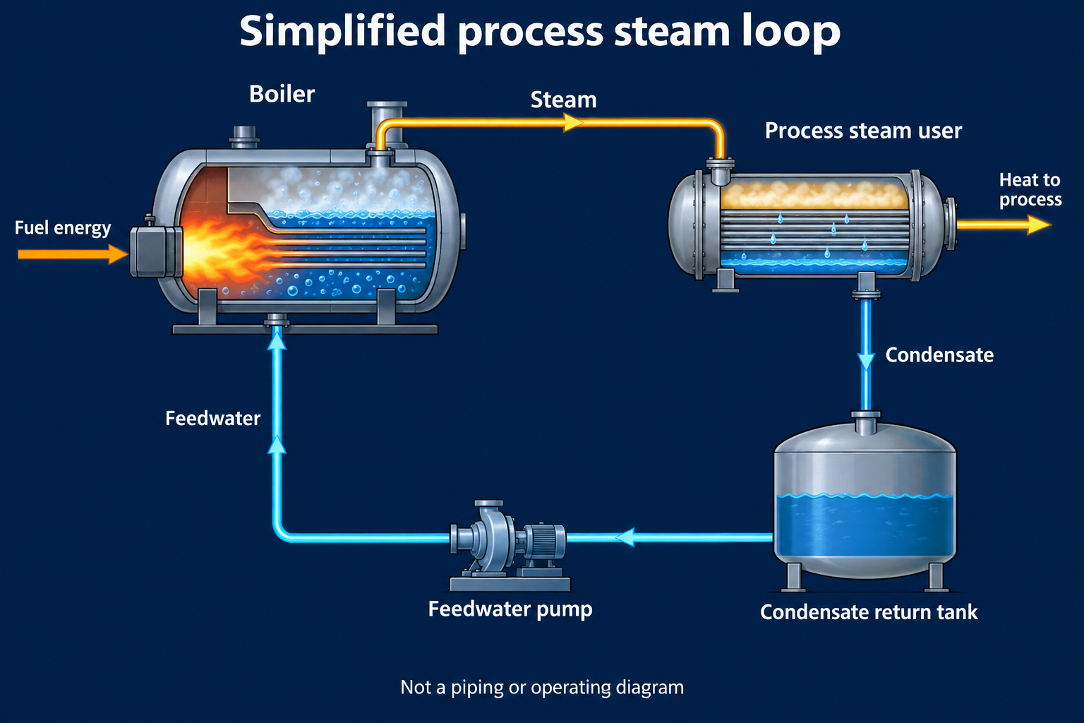
Follow the diagram, then watch the boiler introduction.

Simplified loop: fuel heats the boiler; steam supplies a process; condensate returns through a tank and feedwater pump to the boiler.
Original AI-assisted learning illustration. Amber shows steam and heat; cyan shows water. Safety valves, steam traps, treatment and controls are omitted. This is not a piping or operating diagram. Open full-size diagram ↗

Steam boilers: the inside story

Part 1 introduces an operating firetube boiler. Use it to connect the equipment in the diagram to a real boiler.

Loads YouTube only when you choose to play.

Watch on YouTube ↗

Video: Spirax Sarco. English; use the player’s available captions. If the embedded player is unavailable, use the YouTube link.

What to look for

Identify where heat enters, where steam collects, and where water returns. Compare the equipment shown with your own plant’s approved drawings.

07

Low-pressure boiler: erection to operation

A practical learning roadmap, daily observation checklist and fault-response templates.

Training guide · not an approved plant SOP

For steam-boiler learning. Hot-water boilers and different fuels require different procedures. Before use, a competent boiler professional must adapt and approve the material for the exact equipment and local requirements. Even low-pressure steam can cause severe burns and stored-energy injury.

Always use the site emergency plan for an active incident. Never bypass an interlock, alter a safety setting or attempt work on hot, energized or pressurized equipment from these notes.

From delivery to final handover

1 · Define the installation

Identify the boiler model, serial number, steam or hot-water service, fuel, design pressure and approved operating range. “Low pressure” is not a universal regulatory exemption. Confirm applicable local requirements with the responsible authority.

Record / hold point: Create an equipment register, approved drawings list and responsibility matrix. Record the OEM manual revision and commissioning contact.

2 · Receive, inspect and store

Match delivered items to the packing list and drawings. Record transport damage, loose accessories, blanked connections and missing documentation. Protect openings and store components to the manufacturer’s instructions.

Record / hold point: Receipt inspection, photographs, non-conformance list and release for installation.

3 · Foundation and erection

A qualified installation team verifies foundation capacity, level, anchor locations, service clearances, access, ventilation and drainage against approved drawings. Lifting requires an engineered plan and rated lifting points.

Record / hold point: Survey report, lift authorization and signed mechanical installation inspection. Do not use this lesson as a rigging plan.

4 · Connect services

Review steam, feedwater, condensate, fuel, flue, blowdown, electrical and control connections against the approved design. Check identification, supports, thermal movement allowances and safe discharge arrangements. Qualified trades perform the work.

Record / hold point: As-built drawings, material records, electrical inspection and connection checklists. No field changes without engineering approval.

5 · Inspect before commissioning

Close installation defects. Confirm instruments and protective devices are identified, documented and ready for approved testing. Required pressure tests, cleaning and treatment are specialist activities under written procedures.

Record / hold point: Inspection releases, calibration records, test certificates and an agreed list of any outstanding restrictions. Never substitute an improvised pressure test.

6 · Commission under OEM supervision

Use the model-specific commissioning plan. It defines filling, venting, purge and ignition sequences, warm-up, combustion setup and protective-function tests. Authorized personnel prove these functions and record results.

Record / hold point: Signed commissioning sheets, baseline readings and demonstrated trip functions. This overview deliberately supplies no generic valve sequence, purge time or setpoint.

7 · Demonstrate stable operation

The commissioning team checks performance at approved operating conditions, confirms utilities and controls work together and trains operators. Any abnormal trend is investigated before acceptance.

Record / hold point: Acceptance report, approved operating envelope, alarm-response list and operator training record.

8 · Handover and maintain

Transfer manuals, drawings, inspection schedules, spares information and emergency contacts. Assign responsibility for shift records, water chemistry, defect closure and periodic examinations.

Record / hold point: Formal handover with named signatories. Shutdown, lay-up and restart also require approved procedures.

Small details for the daily round

Use the site’s approved frequency; this page does not prescribe hourly or daily testing of safety devices. Record readings with units and time, compare with the approved range and previous shift, and escalate deviations.

Common problems: safe response and resolution workflow

Each card separates the immediate response, evidence for the specialist and the release condition. Repairs and restart belong to authorized personnel using the OEM procedure.

Low or uncertain water level

Immediate response: Treat a low-water alarm or unreliable level indication as safety-critical. Follow the approved emergency shutdown procedure from a safe location and call the responsible operator. Do not repeatedly reset a trip.

Checks and resolution: Record the alarm sequence and available level/feedwater trends without delaying the response. A competent person investigates the feed system, indication and controls. Do not add water to a suspected dry or overheated boiler; obtain specialist direction.

Return to service: Cause established, equipment assessed, protective functions verified and restart explicitly authorized.

High pressure or a lifting safety valve

Immediate response: Keep clear of discharges. Follow the site emergency response and alert the responsible operator. Never gag, isolate, adjust or defeat a safety valve.

Checks and resolution: Preserve pressure and firing trends for the authorized controls/boiler team. An apparent gauge error must not be assumed to explain away an alarm.

Return to service: Fault repaired and pressure control/protection checked under an approved test procedure.

Flame failure or repeated burner lockout

Immediate response: Leave the lockout in place and contact the authorized burner technician. Repeated reset attempts can create a hazardous fuel accumulation.

Checks and resolution: Record the displayed code, time, operating condition and preceding events. The technician checks fuel, ignition, flame detection and interlocks using the OEM diagnostic procedure.

Return to service: Cause resolved; authorized technician completes the specified restart checks.

Fuel smell, smoke, fire or suspected combustion-gas exposure

Immediate response: Withdraw to a safe area, warn others and activate the site emergency plan. Do not investigate a suspected fuel leak with a flame or operate nearby switches.

Checks and resolution: Only the emergency response team or qualified personnel may assess the area and isolate hazards under the site plan.

Return to service: Area declared safe and the affected system formally released for service.

Banging or water hammer

Immediate response: Keep away from the affected pipework and report immediately. Do not attempt to cure hammer by randomly opening valves or drains.

Checks and resolution: A qualified team reviews drainage, traps, supports and startup/load history after safe isolation where required.

Return to service: Defect corrected and controlled return to service approved.

Wet steam, foaming or unstable level

Immediate response: Notify the responsible operator and follow the approved response if level becomes unreliable. Avoid guessing at chemical dose or blowdown duration.

Checks and resolution: Trend load, level and representative water-test results. Water-treatment and boiler specialists assess contamination, chemistry and carryover.

Return to service: Water quality and level behavior meet the approved criteria; corrective action documented.

Feed pump noise, vibration or poor delivery

Immediate response: Report the change promptly; if water supply or level is threatened, use the approved shutdown response. Do not work on a running pump or open a hot pressurized connection.

Checks and resolution: Log available suction/discharge readings, tank level, motor status and the onset time. Maintenance investigates under isolation and permit controls.

Return to service: Pump function, system condition and boiler water supply verified before release.

Steam pressure lower than usual

Immediate response: Check recorded pressure against the approved range and report the deviation. Low pressure alone does not identify a burner fault.

Checks and resolution: Compare demand, firing indication, fuel use, feedwater conditions and meter trends at matching times. Use authorized instruments; do not increase limits or bypass controls to recover pressure.

Return to service: Responsible operator confirms the cause and stable operation within approved limits.

Water chemistry outside its approved range

Immediate response: Report the actual test result, unit, sample location and time. Follow the site chemistry response, including any operating restriction.

Checks and resolution: Confirm sample handling and instrument status with trained staff. A water-treatment specialist determines corrective treatment or blowdown.

Return to service: Repeat valid results satisfy the site specification and the responsible person authorizes continued service.

Steam/water leak, electrical trip or power loss

Immediate response: Keep clear of leaks and electrical hazards. Follow the approved trip/power-loss response; do not tighten a leaking joint under pressure or improvise a restart.

Checks and resolution: Record affected equipment and alarms. Authorized personnel isolate, verify safe conditions and repair the fault using the applicable permit.

Return to service: Repair inspection, restored utilities and restart authorization recorded.

Reusable SOP and shift-log template

Document: SOP ID • revision • equipment tag/model • scope • author • reviewer • approval date.

Before work: competent roles • hazards • permits/isolation • approved instruments/PPE • prerequisites • source manual and drawing revisions.

For each approved step: action • expected indication/range • stop condition • response • responsible person • record/sign-off.

For each shift entry: date/time • reading and unit • approved range/reference • alarm/observation • action • person notified • defect/work-order number • next review • handover acceptance.

Closure: verified cause • repair/test evidence • outstanding restrictions • restart authorization • revision lessons.
Further reading: HSE boiler safety management · Operating-procedure principles · Boiler water · Steam drainage. UK guidance supports general learning; it does not establish local compliance.

08

Study lab: calculations, trends and troubleshooting

Build confidence by explaining the evidence behind a decision.

Free practice material

Use these examples to learn the method. Compare every plant reading with the approved range for that exact boiler; the examples do not provide operating limits or instructions to change controls.

Steam duty: from mass flow to heat rate

Heat rate is found from mass flow multiplied by the enthalpy rise. If 2,000 kg/h of feedwater gains 2,360 kJ/kg, the heat transferred is 4,720,000 kJ/h. Divide by 3,600 to express this as about 1,311 kW.

Check before concluding: source of the enthalpy values, steam pressure/condition, feedwater temperature, meter basis and measurement period.

Fuel-to-steam ratio: a fair comparison

A shift using 5,000 kg of fuel to make 40,000 kg of steam has a ratio of 125 kg/t. A later shift using 5,400 kg for 48,000 kg steam has 112.5 kg/t. The second ratio is 10% lower.

A lower mass ratio can be encouraging, but it does not prove efficiency improved. Compare fuel heating value and moisture, steam condition, feedwater temperature, blowdown, meter accuracy and load pattern.

Simple boiler efficiency teaching example

For 6,000 kg/h of steam with an enthalpy rise of 2,400 kJ/kg, useful output is 14,400,000 kJ/h. If fuel input is 1,000 kg/h at 20,000 kJ/kg, the example efficiency is 72%.

Formula: useful heat output ÷ fuel heat input × 100. Use a consistent fuel basis; real assessments require validated measurements and the plant method.

Blowdown balance: why concentration matters

In a simplified steady-state example, 9,000 kg/h steam production and a concentration factor of 10 gives a blowdown flow of 1,000 kg/h. Feedwater is then approximately 10,000 kg/h.

Real chemistry control is based on approved sampling, water-treatment advice and the boiler’s limits. Never choose a blowdown duration or rate from a generic example.

Condensate recovery: estimate recovered sensible heat

For a 1,000 kg/h return that is 55°C warmer than incoming make-up water, use 1,000 × 4.18 × 55 ÷ 3,600. The estimated recovery is about 63.9 kW.

First confirm the return is suitable for reuse. Contaminated condensate can damage the boiler-water system.

Pump power: separate hydraulic power from motor input

For 10 L/s lifted 40 m, hydraulic power is approximately 1,000 × 9.81 × 0.01 × 40 = 3.92 kW. At 70% pump efficiency, shaft input is about 5.6 kW before considering motor losses.

Flow, head, density and efficiency determine the answer. Do not operate a pump outside the manufacturer’s approved range.

How to investigate a changed trend

  1. State the observed change with time, unit, load and source.
  2. Check whether the reading is plausible using an independent approved indication or known process relationship.
  3. Compare related trends at the same time: fuel, air, draft, steam demand, feedwater, level and alarms.
  4. List more than one possible cause. Do not label the first correlation as a confirmed fault.
  5. Escalate under the approved response procedure; record the action and preserve the evidence.
Practice case: steam pressure falls during a load increase

Given: steam demand rises, pressure trends down, firing indication rises, feedwater level is stable, and the fuel-flow indication is unchanged.

Reasoning: this can suggest a fuel supply, metering, combustion or capacity constraint, but it is not a diagnosis. Verify the instruments and compare fuel availability, combustion readings and interlock/alarm history.

Safe response: the responsible operator follows the approved load-management and escalation procedure. Do not bypass protections or adjust setpoints based on this case.

Revision checklist

Can you trace fuel, air, water, steam, condensate and flue gas through a simple system? Can you explain why a reading might be wrong, what another indicator would help, and who is authorized to make the correction?

UNI

University lecture references

Use these open courses to strengthen the theory behind the plant notes.

These are external learning resources from universities. They complement this practical guide; follow the lecturer’s course sequence and your own approved plant procedures.

Power Plant Engineering · IIT Roorkee / NPTEL

Steam power cycles, fossil-fuel steam generators, boiler performance, coal and ash handling, feedwater treatment, turbines, condensers, instrumentation and environmental topics.

Open the IIT Roorkee course ↗

Power Plant System Engineering · IIT Guwahati / NPTEL

Power-plant systems, steam cycles, gas turbines, combined cycles, hydro systems, renewable generation and energy storage.

Open the IIT Guwahati course ↗

Engineering Thermodynamics · IIT Madras / NPTEL

Core concepts, heat and work, pure substances, steady-flow control volumes, entropy and thermodynamic cycles.

Open the IIT Madras course ↗

Basic Thermodynamics · IIT Kharagpur / NPTEL

First and second laws, properties of pure substances, vapor and gas power cycles, and reacting systems.

Open the IIT Kharagpur course ↗

Introduction to Heat Transfer · MIT OpenCourseWare

Fundamentals of conduction, convection and radiation, with problem-solving methods useful for understanding boiler and heat-exchanger performance.

Open the MIT course ↗

Advanced Thermodynamics · MIT OpenCourseWare

Lecture videos covering first- and second-law efficiency, entropy, equilibrium, transport and energy-system applications. Best after learning the basic cycle concepts.

Open MIT lecture videos ↗

Availability, enrollment dates and certificates are controlled by each university platform. Course links are provided for study reference only.

01

Plant energy & steam cycle

A boiler utility converts the chemical energy in fuel into heat, then transfers that heat to water to make steam for a process or turbine.

Read the cycle in order

  • Fuel and combustion air enter the furnace; combustion releases heat.
  • Water absorbs heat in the economizer, evaporator/water walls, and other heating surfaces.
  • Steam leaves the boiler at a controlled pressure and temperature for its user.
  • Where condensate is returned, it is checked, collected, and sent back through feedwater treatment.

Keep these quantities distinct

Pressure indicates the force of steam in the system. Temperature indicates its thermal state. Saturated steam temperature depends on pressure; superheated steam is hotter than saturation at that pressure.

Load is steam demand or output. Specific fuel consumption compares fuel mass with steam produced; state the units and fuel basis whenever reporting it.

02

Boiler systems

Each pressure part and auxiliary has a job. Stable steam production depends on coordinated water level, firing, draft, and heat transfer.

Main equipment and purpose

SystemPurposeWatch
Drum / steam spaceSeparate steam from water and provide inventoryLevel, pressure, carryover
Water walls / evaporatorAbsorb furnace heat and generate steamCirculation, deposits, leaks
SuperheaterRaise steam temperature above saturationOutlet temperature, tube condition
EconomizerRecover flue-gas heat into feedwaterInlet/outlet temperatures, leakage, fouling
Air heater (if fitted)Preheat combustion airAir-side / gas-side pressure drop

Three controls to understand

Drum level: low level can threaten tube cooling; high level can carry water into steam lines. Follow approved protections and operating limits.

Combustion: match fuel and air to demand while maintaining stable flame/bed and acceptable emissions.

Draft: fans and dampers keep furnace pressure and gas flow within the design range.

Field habit: check the indicated value, its trend, and the instrument's condition before acting.
03

Combustion and efficiency

Combustion performance is a balance: enough air for complete burning, good mixing and residence time, and heat transfer that keeps useful energy in the boiler.

What changes the result?

  • Fuel moisture, size, ash, volatile matter, and heating value.
  • Fuel distribution and bed depth across the grate or furnace.
  • Primary and secondary air distribution, leakage, and excess air.
  • Load, soot or ash deposits, refractory condition, and heat-transfer surface cleanliness.

Use indicators together

Oxygen and carbon monoxide trends help assess combustion, but neither alone proves efficiency. Read them with load, fuel feed, draft, furnace condition, ash loss-on-ignition, and flue-gas temperature.

High stack temperature can point to poor heat recovery, fouling, excess air, leakage, or measurement error. Confirm the operating condition and instruments before concluding.

04

RO, softening & condensate

Water treatment protects pressure parts from scale, corrosion, and deposits. Sampling quality and representative points matter as much as the treatment equipment.

Typical treatment path

Raw water → pretreatment / filtration → reverse osmosis (where installed) → softening or polishing as designed → deaeration / feedwater conditioning → boiler.

Condensate should be checked before return. A contaminated return can introduce oil, salts, or process chemicals into the boiler circuit.

Parameters to trend

  • Hardness: indicates risk of scale-forming calcium and magnesium.
  • Conductivity: indicates dissolved ionic material; interpret against the correct sample point and limit.
  • pH: affects corrosion control; use the site chemistry programme's target.
  • Silica, dissolved oxygen, phosphate, and alkalinity where the boiler programme requires them.

Use the plant's approved chemistry limits and Nalco/OEM guidance. Limits vary with pressure, treatment regime, and sample location.

05

Fans, pumps & fuel handling

Auxiliaries keep the boiler supplied with fuel, air, and water, and remove ash and flue gas. Their failures can quickly become boiler constraints.

Equipment map

EquipmentFunctionUseful checks
FD fanSupplies combustion airFlow/pressure, vibration, bearing temperature
ID fanMoves flue gas and maintains draftFurnace draft, vibration, damper response
Feedwater pumpDelivers water against boiler pressureSuction, discharge, flow, seal and bearing condition
Fuel feeder / conveyorMoves and meters fuel to the furnaceDistribution, blockage, speed, chain condition
Ash conveyorRemoves bottom or fly ashFree movement, chain/drive load, hot spots

Think in cause and effect

A rising fan current may result from increased flow, changing system resistance, a mechanical issue, or an electrical issue. A pump pressure change may result from flow, suction condition, valve position, wear, or instrument error.

Compare the affected equipment with its process readings and recent maintenance history. Use approved isolation and permit procedures before inspection.

06

Operating checks & response

Use a repeatable round to spot drift early. Record actual readings, units, time, load, and any abnormal condition.

01Confirm steam pressure, temperature, flow, and demand against the normal operating range.
02Verify drum level, feedwater flow, pump condition, and deaerator/feed tank status.
03Check fuel quality and flow, feeder distribution, bed or flame stability, and ash condition.
04Trend oxygen, draft, fan current, vibration, and flue-gas temperature together.
05Check water chemistry and treatment equipment against approved site limits and sampling frequency.
06Inspect for leaks, hot spots, unusual noise, conveyor blockage, and failed or bypassed alarms.
07Compare readings with the previous shift; investigate unexplained changes before they become trips.
08Report abnormal conditions, actions taken, and pending work at shift handover.
Safety first: Follow site procedures, OEM instructions, permits, lockout/tagout, and emergency response rules. This guide supports learning and does not replace approved operating instructions.

Read in your language

English and Hinglish are available using the buttons above. For other languages, open a machine-translated copy with Google Translate.

Open translation ↗

More languages: use Google Translate’s full language list ↗

Machine translations may misinterpret technical terms. Compare with the English original and use approved plant instructions. Availability varies by region.